SPECTROGRAPHS AND RELATED INSTRUMENTS
Spectrographs -
Entrance Optics
- CCD
- Atmosphere
- Mechanical Flexures
- Ref Lamps
Spectrographs
In order to build an optical spectrograph you need to put along the optical path a dispersing element
that send the light of different wavelength in different directions.
There are two main classes of dispersors: Diffraction gratings and prisms.
The prism is more easy to build and have been used since 17th century for the dispersion of the light.
In this page we will describe both the prism and grating spectrographs that we have built and that we use to record the spectra shown in all the other pages.
|
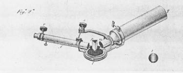
|
Picture 1: The prism spectrometer of the italian astronomer Donati, around 1860.
|
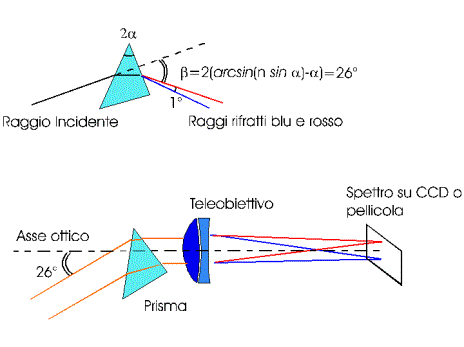
How to build an objective prism spectrograph
The objective prism spectrograph that we realized uses as a dispersor element the inexpensive prism of an old
binocular or diagonal. The prism should be mounted, as shown in picture 2, allowing the light to
enter from the short side and exiting from the bigger face, thus using a 45 degrees apex angle.
As a telescope, can be used a 200 mm or so telephoto lens, better if coupled to a CCD camera.
|
|
Picture 2: Layout of a simple objective-prism spectrograph that uses the 45 degrees prism
of an old diagonal or binocular.
|
A prism of glass or fused silica (quartz), properly used, can deviate the incoming light at different
angles, depending on its color or wavelenght.
Flint glass has a bigger dispersive power but in a binocular or diagonal you will find a kind of crown glass called BK7.
BK7 has a refraction index equal to 1,53 in the deep blue. In the yellow its value goes down to 1,519 and in the red become 1.513.
The minimal refraction angle, as shown in the picture 2, that is the best optical configuration of the prism,
can be obtained from the refraction law. At minimal refraction angle, the incoming light forms the same angle with the face of the prism as the
outgoing light.
For a 45 degrees BK7 prism, the minimal deviation angle is 26 degrees. Thus the telephoto
lens with the prism will look at a sky region that is 26 degrees apart from that defined by the optical axis of the telephoto lens.
The deviation angles of the light calculated in the red and in the blue differ 1 degree. This means that the spectrum
will be 4 mm long on the detector if the focal lenght is 200 mm.
With such a simple objective prism spectrograph, you can't dream of measuring the red shift of galaxies or the doubling of the
spectral lines of binary stars but it is possible to distinguish the spectral class of many stars.
Red stars like betelgeuse, Mira Ceti or Antares will show the classical band spectrum due to TiO oxides, while A stars like Vega and Sirius
will show the lines of the Balmer series of hydrogen.
With a normal F/4 telephoto lens and a 25 mm prism (that reduces the telephoto lens at F/8) can be recorded spectra of 6th magnitude stars.
Design of a grating spectrograph
The diffraction gratings
A simple diffraction grating is a mirror grooved with parallel lines (from 10/mm to many thousands/mm)
rigorously parallels and equally spaced.
The behaviour of a parallel light beam incident on a diffraction grating is shown in picture 3.
The diffracted light from each line interferes with the diffracted light of all other lines
and a reflected beam is obtained only at those angles that allow that all the contributions sum up in phase.
The grating can work also like a mirror, when the phase difference between the light reflected by different
lines is zero. This reflection is called, in the optical gergon, "zero order".
In the "firs order" diffraction, the path lenght difference of the light diffracted by two neighboring lines
equals exactly one wavelength of light.
In the "second order" diffraction, the path lenght difference of the light diffracted by
two neighboring lines equals exactly two times the wavelength of light and so on for
the higher orders.
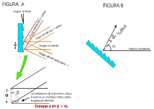
Picture 3: Diffraction of light from a plane grating
The condition for constructive interference that we can obtain looking at picture 3A
is a sin b = n
l.
For numerical calculation of diffraction angles we must pay attention to express a in the same units as the wavelenght
l.
In the more general case (picture 3B), putting the grating at an angle a
with the incoming light, the constructive interference relation become:
a (sin a +
sin b) = nl.
From this last formula we can obtain the expression for the angular dispersion (be careful in
calculation to the angles that must be expressed in radians) Db/Dl
= n / a cos b.
We can see that dispersion is proportional to the inverse of the groove spacing distance,
thus it increases with the number of lines of the grating, for a given order.
Dispersion allows to calculate the spectral field and resolution of a spectrograph although
resolution is a function of many other critical parameters, like slit opening, the angle
b and the focal lenght of the focusing
optics on the detector.
Spectrograph resolution should not be confused with grating resolution.
The theoretical resolution of the grating is l/Dl
(where Dl is the spectral distance between two
lines that are just resolved) equals the number of grating lines that are illuminated by the incoming beam.
Resolution obtained with gratings can achieve very high values. As an example, for a 1200 l/mm
grating in a 10 mm beam, the resolution is 12000, that is equivalent to 0,4 ┼ at 5000 ┼.
The grating that are more useful for an astronomical spectrograph has a line spacing that ranges
from 300 l/mm to 1800 l/mm.
If the angle b remain within 20 degrees,
the disperions obtained are 1,7░/1000 ┼ and 6,7░/1000 ┼ respectively.
These values must be compared with the dispersion of a 60░ flint prism that can achieve
2░/1000 ┼ in the near UV but only 1░/1000 ┼ in the green and 0,3░/1000 ┼ in the red.
Nevertheless prisms have the advantage that all the light goes in one only spectrum, while for gratings
the light is shared between in multiple order spectra and in the specular reflection (zero order).
This would result in a serius loss of efficiency if the line profiles were not shaped in order
to send the maximum of light on a particular order (usually the first) while others remain faible.
The wavelenght for which the grating is optimized is indicated as "blaze wavelength" and it is
necessary to take care about this parameter in ordering a grating. The blaze wavelength can change
a lot from the specified if the grating is used at high angles.
You can find more details on the following books:
Astronomical Optics - Schroeder - Academic Press
At the end some practical information.
The biggest suppliers of diffraction gratings are Richardson in the US and JY in France.
You can purchase good quality grating at fair prices in Edmund Scientific catalogue of
.
Price is around 100$ for a 30x30 mm grating and 150$ for a 50x50 mm.
Other parts of the spectrograph: Slit, collimator, camera
An objective-prism spectrograph cannot be easily suited on big aperture, dispersion
is low and cannot be applied to the spectroscopy of extended sources because it has not a slit.
To overcome all these problems we have developed (and still we are developing) a grating
spectrograph for the Cassegrain focus of the 60 cm reflector of ur observatory.
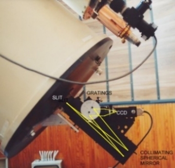
The instrument is described in picture 4.
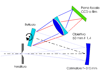
|
|
Figura 4: Schema dello spettrometro a reticolo da noi realizzato
|
A micrometric slit (0-3 mm opening at 0,01 mm step) has been mounted onto the focal plane.
A spherical mirror with focal lenght 310 mm has its focus on the slit and send a parallel beam
onto the grating.
For a bigger dispersion range, two gratings are permanently mounted.
The gratings have 1800 and 600 lines/mm, both blazed for maximum efficiency (about 60%) at 5500 ┼.
The beam diffracted by the grating (1800 l/mm has a spectra dispersion of 55 ┼ /degree and the 600 l/mm
about 200 ┼/degree) are collected by a F1,4 50 mm camera lens and focused onto the Starlight Xpress MX5 CCD
detector (500x290 pixels) or the photographic film.
Gratings can be turned in order to select the central wavelength.
The 1800 l/mm grating has a spectral range 0-7000 ┼ while the 600 l/mm grating allows to record spectra up to
1 mm (10000 ┼).
The use of the photographic plate as a detector allows to record the full spectrum in one shot but
the CCD is by far more sensitive and has a more extended spectral range (12 bit). To these
advantages must be added the extended spectral sensitivity also to the near infrared up to
1 mm (10000 ┼).
As the size of the chip of our CCD (SONY ICX055BL) is 3.67 mm, the spectral coverage for each exposure results
300 and 1200 ┼ respectively for the 1800 and 600 l/mm grating. Thus in order to obtain the full
spectrum it is necessary to glue together a number of spectral regions (practically about 12 for
the 1800 and 4 for the 600).
The spectral resolution that we obtain is 0,6 ┼ (1800 l/mm grating) and 2,6 ┼ (600 l/mm
grating) when the slit is closed at 60 mm or less.
The value of 60 mm is chosen because it is
equivalent to 1 arc second on the sky and to 1 pixel on the CCD (infact there is a magnification
of 6 times between focusing and collimator optics).
A further reduction of the slit size can't improve the spectral resolution until when it is not increased
the focal length of the camera lens.
Many spectra among those shown in these pages have been recorded with a previous version
of the spectrograph equipped with an achromat f=100 mm as collimator and a 900 l/mm grating.
Resolution was 2 ┼.
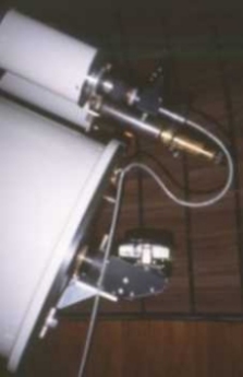
Both instruments are shown into picture 5.
Picture 5: Our spectrographs at the Cassegrain focus of the 60 cm reflector.
At left with 900 l/mm grating, 100 mm collimator achromat and photographic camera
At right with grating 600/1800 l/mm, collimator mirror f=310 mm and CCD detector.
|
|